Warps are the centerpiece of 2D+ previews and impressive headlines. In Printess everything can get warped, stretched and distorted while staying adjustable and personalizable. In this example, we have used our magic Mesh Warp. This wrap lets you apply the texture of a crumpling pillow to whatever area you’d like on a surface. We’ve added a Single Line text feature to the frame containing the frog image.
Every warp has Transformer icons (as seen below) that set on which feature of a frame a warp should be applied. In this case, we activated the Text and the Image icons.

The Mesh is thus applied to both the image (Printess frog) and the text (Julia):

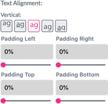
Text position is very important for ensuring professional looking outcomes. That’s why we’ve added the Text Alignment settings for Single Line texts directly to the bottom of the Warp tab. If something does not look as intended, merely adjust the alignment settings until perfection has been achieved.
If a frame has any warps enabled, the Wrap icon in the features panel will stay magenta to indicate this. Warp effects can be integrated into near-infinite combinations, so try not to get lost while experimenting!
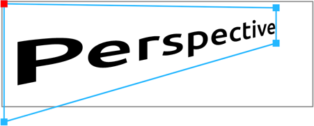
Perspective transformation gives you instant depth. Click the Close Editor button or press Esc to switch back to normal view.
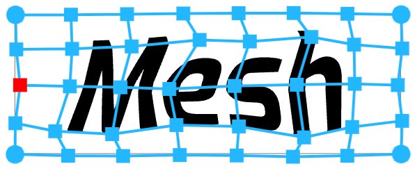
Mesh is ideal to apply text and graphics onto uneven surfaces. You can also adjust the number of needed rows and columns, creating more adjustable intersect points, at any time.
Tip: Mesh calculation speed is significantly higher when keeping all mesh points inside the Frame.
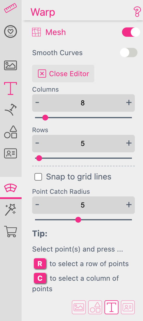
While adjusting the grid you can select any point in the grid and press the R key to select a complete row of points or C for a complete column. Click the Close Editor button or press Esc to switch back to normal view. You can continue to edit the grid at any time by clicking  .
.
Point Catch Radius
You can define a radius around the point you would like to move.
If you set it to “1” you can only move the single point you have selected.
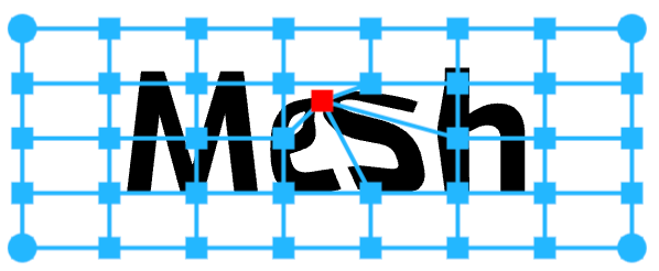
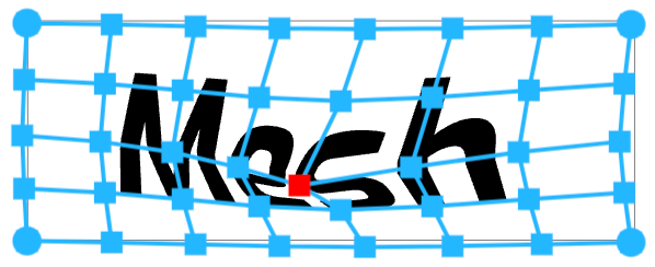
The larger you define the Point Catch Radius the more surrounding points are moved as well.
Notice: When using Single Line text with a Stroke in conjunction with Mesh Warp, it is required to add paddings that are larger than the stroke width to ensure the stroke is not cut off.
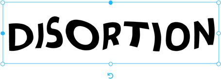
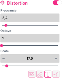
Distortion provides a wave-like transformation.
Frequency determines the number of waves present.
Octave provides an additional sub-frequency.
Scale sets the overall amplification of the warp.
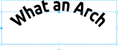
The Arch transformation puts your design into a circle with a variable slice bending upwards or downwards.
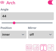
Angle is used to control the slice and whether to bend upward or downward.
Position (Inner, Outer) controls inside or outside bending.
Mirror - Mirrors the direction.
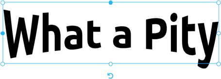
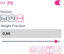
Pit projection is used to mimic a round wall with perspective. Pit thereby offers three modes of distortion (Upper, Lower and Squeeze distortions). This Warp is especially sensitive to text positioning.
Upper - Positioning of the top text is recommended.
Lower - The vertical text alignment should be set to the bottom baseline.
Squeeze - Works best with centered text.
Height Fraction - Amplifies the height of the Pit.
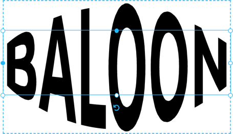
Arc projects on top of a sphere/half shell.
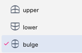
Arc offers three modes: upper, lower & bulge.
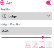
Height Fraction - Amplifies the height of the selected Arc mode.
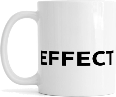
As projecting something on mugs looks to be a common task in the industry - voillá! Printess has developed a specialized Warp effect to achieve this with ease.
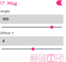
Angle - Will set the visible angle (max. 180°).
Offset Y - Sets the y-offset according to the selected viewing angle.
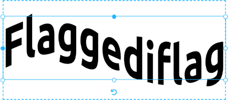
The Flag Warp applies a vertical sin-wave translation.
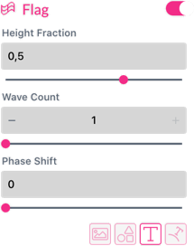
Wave Count - Controls the number of full waves.
Phase Shift - Shifts the wave.
Height Fraction - Sets the wave amplitude.
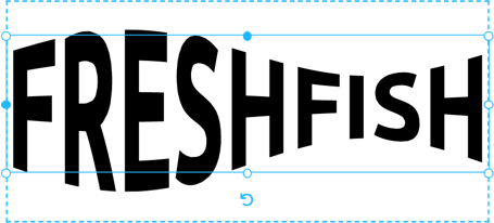
The Fish Warp is a sin-wave scaling.
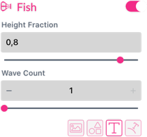
Wave Count - Control the number of waves.
Height Fraction - Sets the amplitude.
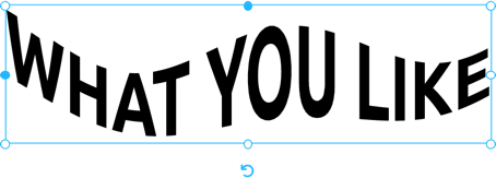
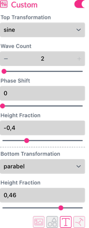
The custom warp allows users to warp the top of the frame with a different formula than the bottom. Choose from Sin, Cos, Parabolic, Inverse Parabolic, set the Phase Shift and Wave Count (for Sin, Cos). Set the Height Fraction for amplitude. These parameters can be independently defined for the top and bottom of a frame, thus giving one a huge variety of options for the final appearance.